Microcontroller Programming
Arduino Traffic Light Simulator
The aim of the project was to build an interface to control output devices such as LEDs and Buzzer using micro-controller programming.
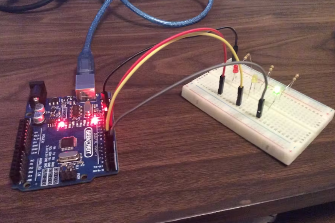
This project uses an Arduino and some LEDs to replicate a traffic light.
It uses code as an internal timer and continues to run until you cut the Arduino's power supply.
The materials required are as follows:
1. Arduino Uno
2. Breadboard
3. Jumper Wires
4. LEDs
5. Resistors
Steps
Step 1: Supply power to the breadboard.
Insert one side of the jumper wire into GND on the board. Lead the other side to the breadboard. Put it on the far right column on the breadboard, at the top. This is the ground column.
Step 2: Adding the LEDs.
Take out your LEDs and resistors. Place one end of the resistor in the column on the right, the same column we connected our jumper wire to. Extend the other end of the breadboard into the main part of the breadboard. Attach the resistor to any row you like. LEDs will go on the same row. Stick one end of the LED on one side of the breadboard, and the other end on the other side of the breadboard. The short end of the LED will go on the side your resistors are on, the right side. Extend the other end of the LED to the right side of the breadboard.
Step 3: Completing the circuit.
Take another jumper wire, put it on the same row that you have an LED on. This is where the wires will go:
Green LED: Port 2, Digital PWM section
Yellow LED, Port 3, Digital PWM section
Red LED, Port 4, Digital PWM section
The file for the Arduino code is here : Code
Conclusion
The above circuit gives the output as an traffic light. The Green, Yellow and Red lights glows one after the other in order for 5 , 2 , 5 seconds respectively. A loop functions runs here calling green light, then yellow light, then red light and then green light again: and the loop continues.
Input and Output Devices
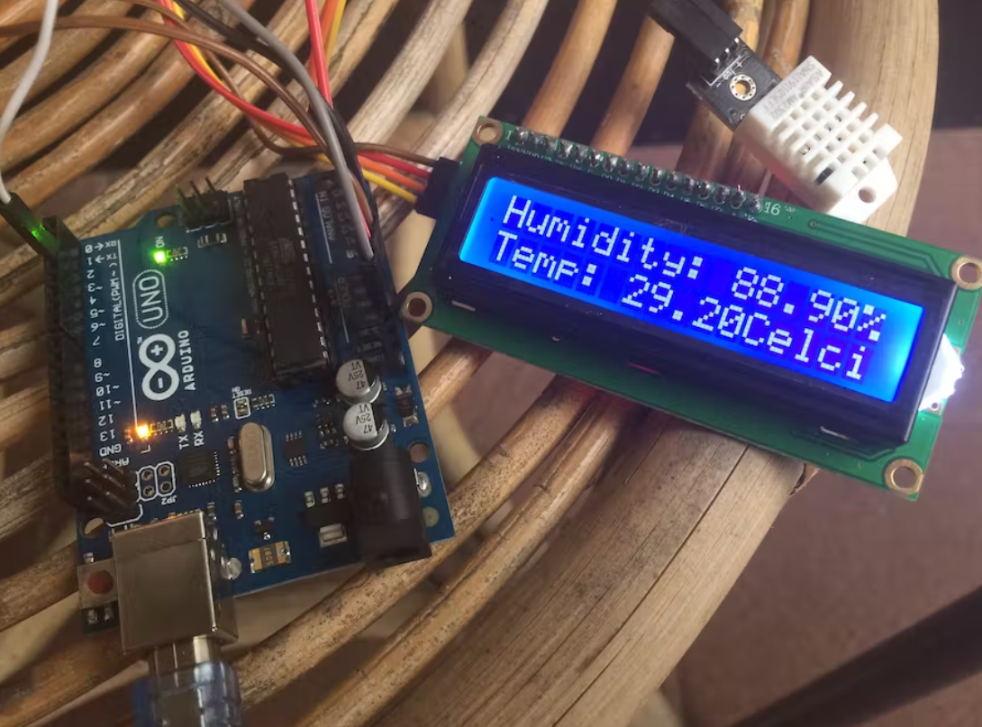
Temperature Monitor
The idea is creating very portable temperature and humidity sensing without making me abandon this project and carry on with finish product of temperature and humidity gadget.
In this project, I abandon breadboard because it Arduino still capable to powering sensor and LCD directly.
The materials required are as follows:
1. Arduino Uno
2. DHT22 Temperature and Humidity Sensor
3. Jumper Wires
4. Liquid Cristal Display with i2c Backpack
5. 9V battery
Steps
Step 1: Configure the LCD
connect SCL to A5
connect CDA to A4
GND to GND
VCC to 5v
Step 2: Connect the sensor to Arduino.
Connect Data Signal to D2 Arduino
Connect VCC to 3v3 Arduino
Connect GND to GND
The working voltage is 3~5v there is no reason to using higher voltage that will need to use a breadboard.
Step 3: Verify and upload the sketch, pull the usb, and plug the battery.
The file for the Arduino code is here : Code
Conclusion
The above circuit gives output with the measure of temperature and humidity of surroundigs. The DHT22 sensor records the temperature and humidity as an input and the LCD shows that input on the screen as an output. Here a loop fumction of measuring temperature and humidity runs, which runs after every 2 seconds and gives us the required data of surroundings.